
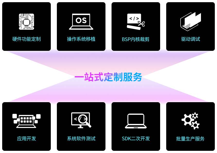
采用成熟、稳定、扩展性强的Linux 4.19 系统,可提供包含系统内核修改、驱动程序移植、应用程序开发和UI界面定制等一整套完整的软件系统定制服务,为产品研产提供安全稳定的系统环境。同时可基于瑞萨e²studio IDE软件开发,支持与亚马逊AWS和微软Azure等第三方平台无缝对接。


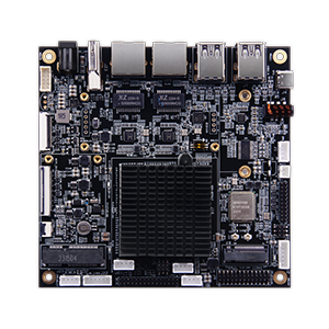
DB-G2L-V2 载板(适用于瑞萨 RZ/G2L SOM)
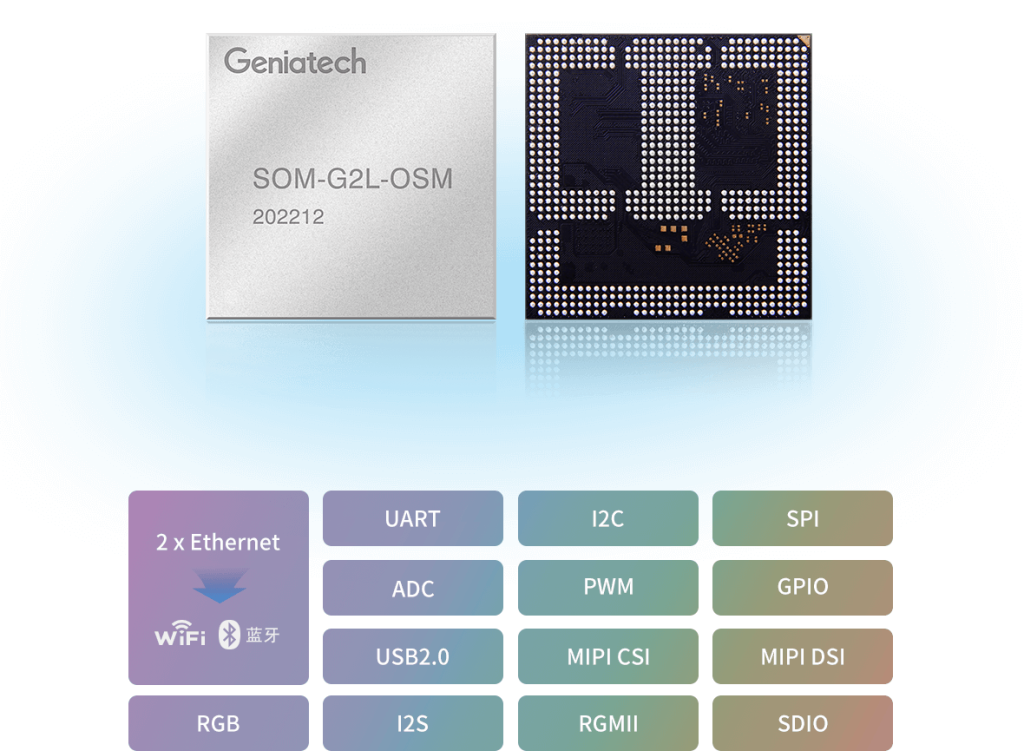
专为瑞萨 RZ/G2L SOM 设计的高性能工业载板,提供丰富的 I/O 接口,支持快速原型开发与系统集成。
- 双千兆以太网(PoE PD)及2路CAN FD接口
- 支持MIPI CSI摄像头及MIPI/RGB液晶屏
- USB2.0主机/OTG、Micro SD卡、4G模块扩展支持
- 音频输入输出:线路输入/输出、麦克风、扬声器
- 多路UART、I2C、SPI、GPIO扩展引脚
- 用于开发测试的JTAG及调试UART接口
- 灵活的12V直流电源输入